
Precision Machining CNC: What Tolerances and Surface Finishes Are Realistic, and How DFM Decides
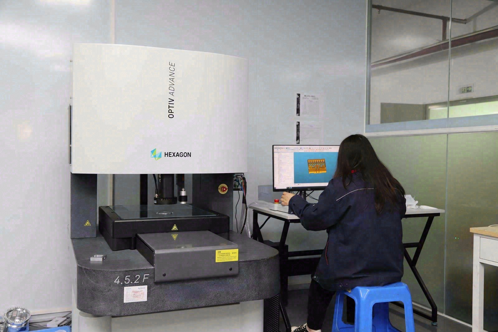
Most drawings ask for more precision than they need, and the machining quote is where that habit gets priced. A tolerance is not a decoration; it is a set of instructions to the machine about feed, tooling, and inspection, and each tightening of the band adds cost to the part whether the function needs it or not. The realistic question is not "how tight can a precision CNC shop go" — the capability is well known — but "which features on your part actually need the tight band, and which finish travels with it." This guide answers both from a precision machining CNC perspective: what tolerances and surface finishes a capable shop holds, how the design-for-manufacturability (DFM) review turns a drawing into a machinable one before the quote is written, and what evidence makes a tolerance claim real.
Why does a realistic tolerance question start with the DFM review, not the machine?
A precision CNC shop can hold very tight numbers — the machine is rarely the limit. The limit is whether the feature is worth the band you put on it, and that judgment is what the DFM review exists to make. An engineer reads the drawing and separates the dimensions that control function — a bearing bore, a press fit, a sealing face — from the ones that simply carry a number someone copied from an earlier print. The first group earns the tight callout; the second is a candidate for a general standard, because tightening a feature that does nothing costs money without buying function.
The tolerance is the DFM lever with the sharpest cost curve. A ±0.05 mm band is cheap; the same feature at ±0.003 mm needs a slower feed, a sharper tool, and a coordinate measuring machine check. When a review relaxes a cosmetic edge from a tight band to a general standard, it removes a finishing pass, an inspection step, and the risk that goes with both — without changing how the part works. This is why the DFM review is the buyer's best tolerance tool: it catches the over-specified callouts before they reach the quote, so the price reflects the precision the part needs rather than the precision the drawing inherited.
Which tolerance bands does a precision CNC shop actually hold, and where does each belong?
Capability on a precision floor runs in a small number of bands, and each one is tied to the process that produces it. CNC milling and turning hold ±0.003 mm on stable, rigid features; precision grinding holds ±0.002 mm on surfaces where roundness and flatness decide the fit. Loose commercial bands — ±0.1 mm or looser — run at standard feed with no special inspection, which is where clearance slots, covers, and non-mating faces belong. The middle bands fill in the gaps: ±0.05 mm for general fits and locating surfaces, ±0.01 mm for precision fits and alignment features that need a CMM or gauge check.
The realistic discipline is selective tolerancing. Put the tight numbers on the two or three dimensions where fit and function live — the bore that locates a bearing, the face that seals, the diameter that press-fits — and let the rest of the print ride on a general standard. The DFM rule is blunt: a feature at ±0.003 mm that only needs to sit against a bracket is a feature paying for precision that no one will ever measure in service. The shop that questions a tight callout is protecting your budget, not dodging the work, and the review should say which bands are machinable as drawn and which are over-specified — the same DFM logic the main precision-machining guide applies to cost and quality across the drawing.
What does ISO 2768 do to a drawing, and why does it make tolerances realistic?
Most prints carry more untoleranced dimensions than toleranced ones, and those untoleranced features still need a limit. ISO 2768 provides it: a note in the title block stating a general class — fine (f), medium (m), or coarse (c) — applies a default band to every dimension without an explicit callout. The drawing says "general tolerances ISO 2768-m," and every unmarked feature inherits the medium-class limit for its size range. Only the dimensions that control function get their own tight number, which is what makes the print readable: you can see which three or four dimensions matter, because they are the only ones carrying numbers.
ISO 2768 is the single biggest DFM shortcut on a print, because it removes the temptation to copy a tight tolerance onto features that do not need it. A drawing that tolerances every dimension individually is usually a drawing that has not thought about which features matter. A drawing that leans on a general class and calls out only the functional dimensions is a drawing the review can read in minutes, and a drawing the shop can machine at normal speed instead of creeping through every feature. When a buyer asks "is this print drawn to ISO 2768, and which class?", the answer reveals how the drawing was made and how much precision it is actually asking for.
Which features on a drawing earn a tight callout, and which defeat it?
Realistic tolerancing starts with feature geometry, because the feature decides whether the band is honest before the machine is even involved. A short, rigid feature — a bore through a solid section, a face milled in one setup, a diameter turned in a chuck — holds ±0.003 mm without theatrics. These are the features a capability statement is really about. Long, slender sections deflect under the cutting tool and spring back, so pushing a turning length past roughly ten times its diameter demands a wider band or a different support strategy. Thin walls flex as the clamp tightens and move when it releases, which is why a thin wall and a tight flatness callout on the same feature are often in conflict. Deep holes wander off position past roughly three times their diameter, and unmachined stock surfaces carry whatever tolerance the raw material holds rather than anything the machine contributes.
None of this means the shop cannot hold fine numbers — it means the realistic tolerance is a feature-by-feature answer. A drawing that calls out tight bands on rigid, short, single-setup features is a drawing the process can hold with margin. A drawing that puts tight numbers on thin walls, deep holes, and unsupported spans is a drawing that will consume its tolerance in deflection before the part is even measured. The DFM review catches these conflicts at the drawing stage, where the fix is a design change rather than a scrap bin, and that is why a reviewed drawing and a realistic tolerance are the same thing.
Surface finish is written as Ra, the arithmetic average of the surface roughness, and it is the callout most often over-specified on machined parts. The realistic ladder is short. A standard machined finish of Ra 3.2 µm comes off a normal milling or turning pass and serves general faces and non-sealing surfaces. Ra 1.6 µm needs a finishing pass at a moderate feed, which suits mating faces and locating surfaces. Ra 0.8 µm demands a fine finishing pass or grinding, and belongs on sealing faces and bearing seats. Ra 0.4 µm and finer requires grinding, lapping, or honing, and is reserved for precision seals and optical interfaces.
The cost discipline is the same as for tolerances: call out the coarsest finish the function allows, and name the specific faces rather than writing "Ra 1.6 all over." A drawing that demands a fine finish on every surface forces the machinist to slow the whole part to deliver one functional face. A drawing that names the sealing face at Ra 0.8 µm and leaves the rest as-machined gets the function at a fraction of the finishing time. The DFM review should flag a finish ladder the part does not need — the same way it flags a tolerance the function does not need — because both are precision you are paying for without a use.
Why should finish and tolerance be read as a pair, not two separate callouts?
Finish and tolerance travel together, and a drawing that treats them as independent numbers is missing the point. A surface held to ±0.003 mm usually needs a finish good enough to measure that dimension reliably — a rough face on a precision bore makes the measurement itself ambiguous. Conversely, a fine finish on a loosely toleranced surface is polishing something that carries no function. The realistic callout pairs the two: the face that seals gets Ra 0.8 µm with a tight flatness or size band, and the face that only mounts gets a standard finish with a general tolerance.
The pairing also extends to coatings. Anodizing grows the surface outward by a few micrometers, which is enough to change a precision press fit — a bore that fits before anodizing can bind after. The DFM rule is to tolerance the finished dimension after anodizing and to tell the shop the finish is coming, so the machinist leaves the allowance and the coating completes the part to print. A part designed to the raw state and finished later is a different part from one designed to the finished state from the start, and the review is where that difference gets caught.
What evidence should back a tolerance or finish claim before the parts ship?
A tolerance on a drawing is a promise; the measurement system is what makes it true. For the features that carry function, ask for the measured values against the callouts — a CMM report that prints each reading next to its nominal — rather than a pass-fail stamp. For surface finish, a claim of Ra 0.8 µm deserves a roughness trace from a profilometer on the face in question; a photograph of a shiny part proves nothing, because polish and roughness are different properties.
Process capability is the third leg of the evidence. Capability at Ppk ≥ 1.67 at the initial study on key characteristics and Cpk ≥ 1.33 on general characteristics. Capability is reported per characteristic: every report names the feature, its tolerance band, the sample size, the sigma method, and the study window. Means the process spread fits the tolerance with margin, so parts come out good by capability rather than by sorting. On a representative length characteristic of 76.1–76.5 mm, the SPC record on this floor shows Cpk = 1.851, with key characteristics held to Ppk ≥ 1.67 initial and general characteristics to Cpk ≥ 1.33. A single good measurement proves one part; a centered, tight run over many parts proves the process. Ask for the SPC chart, not a single number, and ask which instrument measured the features that matter — the answer separates a shop that measures from one that assumes, as the quality and inspection page explains line by line.
Read the tolerance band before you read the index. Cpk is a ratio of the tolerance band to the process spread, not an absolute measure of accuracy. The figure above was recorded on a length characteristic with a 0.4 mm band (76.1–76.5 mm) — wide by design. Hold the same process spread against a ±0.005 mm feature and it fails outright. Ask for the band, the subgroup count and the sampling window on every capability number a supplier quotes.
Frequently Asked Questions
What tolerances can a precision machining CNC shop realistically hold?
CNC milling and turning hold ±0.003 mm on stable, rigid features, and precision grinding holds ±0.002 mm on surfaces where roundness and flatness decide the fit. Loose commercial bands down to ±0.1 mm run at standard feed with no special inspection. The realistic choice is which features earn the tight band — function decides, not habit.
Which surface finish should I write on a machined part?
Ra 3.2 µm for general faces straight off the machine, Ra 1.6 µm for mating and locating surfaces, Ra 0.8 µm for sealing faces and bearing seats, and Ra 0.4 µm or finer for precision seals and optical interfaces. Specify the coarsest finish the function allows, and name the faces rather than writing a finish over the whole part.
Does the DFM review really change what tolerances I should specify?
Yes. The review separates the dimensions that control function from the ones carrying an inherited number, and it flags over-specified callouts before they reach the quote. A bearing bore earns ±0.003 mm; a cosmetic edge does not. The reviewed drawing pays for precision only where the function earns it.
What does ISO 2768-m mean on my drawing?
It is a general-tolerance note that applies a medium-class default band to every dimension without an explicit callout. Only the dimensions that control function carry their own tight numbers, which makes the print readable and the machining normal-speed instead of slowed by over-tightened features.
Do anodizing or other coatings change the tolerances I machined?
Yes. Anodizing grows the surface outward by a few micrometers, enough to change a precision press fit. State the finished dimension after the coating and tell the shop the finish is coming, so the machinist leaves the allowance and the coating completes the part to print.
How is a claimed finish or tolerance actually verified?
With the right instrument: a CMM for size and position against the drawing, a profilometer for roughness on the face in question. Ask for the measured values, not a pass/fail stamp, and for process capability at Ppk ≥ 1.67 at the initial study on key characteristics and Cpk ≥ 1.33 on general characteristics. Capability is reported per characteristic: every report names the feature, its tolerance band, the sample size, the sigma method, and the study window. — the statistical proof that parts are good by capability, not by sorting.
Which quality systems back the tolerance and finish claims at this precision shop?
The shop operates under ISO 9001:2015 (certificate 116024/A/0001/UK/En), IATF 16949:2016 (product design excluded) (131941/A/0001/SM/En), and ISO 14001:2015 (116024/B/0001/UK/En), and verifies incoming material against its mill certificate before stock reaches the machines. The CMM report, the material record, and the SPC data ship with the parts rather than staying in a brochure.
Not sure which tolerances and finishes your drawing should actually carry?
Send the drawing to [email protected] or call +86 13126536955. You will get a DFM review that names which callouts are realistic as drawn, which should move, and what each one costs — before you spend money on precision the part never needed.